Credits for the schematics to Rod Elliott – Elliott Sound Products – The Audio Pages (Main Index)
I needed a second audio system and chose to build an amplifier with integrated Bluetooth audio. So the search began for the right amplifier schematic, BT module and case.
Choosing the amp schematic was pretty easy, as Rod Elliott’s P3A project is tested by a lot of people with very good results. The amplifier will output 60-100W, depending on load impedance (4/8Ω) and supply voltage. While I was there (https://sound-au.com/index.html) I discovered a plethora of audio-related resources and information, highly recommend going through the site. Decided to add to the project the P33 DC protection and muting circuits, and later, after the build was complete, a DC blocker – I’ll go into more details later.
I searched quite a bit for an audio Bluetooth module that fit the bill. I needed a module that had line out level of signal (no headphone amplifier) and antenna connector so I could run a cable to the back of the chassis to an antenna. The module also has PCB antenna but that wouldn’t be sufficient since it will be mounted inside a shielded metal case. I found on AliExpress this great module that also had line in with relay switching between signals (it defaults to line in only if BT is not connected). It has a good quality DAC (QCC5125) and a wide power supply voltage, 8-32V. I also found an external 2.5GHz antenna and cable to connect to the board. One mistake I made was ordering both the antenna cable plug and the antenna socket as female. I solved it by cutting a diode pin to size and using it as a center pin.

The chassis I also found on AliExpress, from Nobsound. It’s a good quality solid aluminum case with thick front plate, big external radiators (too big for what I needed, but you can never have enough cooling, right?), volume knob, power switch on the front and 6 pre-drilled holes in the back (I needed a different location for the holes, more about that later). It has pre-cut vent slots on the upper and lower plate, it ticked all the boxes.

The main transformer is also an important part of the project. I chose a toroidal transformer with Rod’s recommended 25-0-25V secondary winding, 300VA. There are vendors on AliExpress that make custom transformers from the client’s specification. I ordered one and it took 38 days to arrive, probably due to its 3kg weight, as the other components I ordered from AliExpress arrive in about 2 weeks. This is where I started regretting not doing more due diligence on the vendors and quality of components. The transformer arrived in good order and functioned properly but it hummed more than I would have liked an audio amplifier transformer to hum. I ended up replacing it with a Talema transformer from TME.com (I would know of them if you’re from Europe). Talema is known for their high quality transformers, very well suited for audio builds. This one had much lower hum and even lower height. I’ve lowered the noise even more by adding a DC blocker, more about that later.

For the transformer I chose to order a metal cover in the hopes that it would prevent hum induced in the amplifier and wiring. I’ll soon come to understand that the cover does very little to shield against magnetic fields; they are better at electrostatic shielding. In a future project, I’ll probably skip it, it does take some space in the chassis and I didn’t notice a difference in transformer-induced hum in the output when routing the wires properly.

While I’m on the subject of due diligence – had to order replacements for the final transistors and capacitors as well. The ones I ordered from the aforementioned site were clearly counterfeits. In the producer’s data sheet of the transistors they were supposed to have 9 grams, the ones I got weighed only 6.5g, so something was definitely off. Also, the big 10.000μF/63V Rubycon capacitors were rated at 105° C. The manufacturer doesn’t have this combination in its catalog. I ordered others from TME. I wasn’t going to sit and wait for a capacitor to blow up. There are other trusted websites you can order from, Mouser, Farnell or Digi-Key.
Visually, there are only subtle cues, but looking at the parameters you can positively determine if they are fake of not. If you want my advice, buy components like power transistors or big capacitors only from trusted vendors or do strict due diligence when ordering from websites aggregating many vendors with varying degrees of trust.

Block Diagram

The project consists of 2 mono P3A amplifiers fed by the BT module. The amplifiers are powered by a 35-0-35VDC power supply, while the BT module is powered separately by a 15VDC source, to avoid ground loops. The output signal from the amplifiers is fed to relays on the P33 board which switch the speakers between GND and the amp. The DC blocker module is filtering DC from the mains supply to reduce hum on the toroidal transformer.
IMPORTANT – I should also caution you about working with mains voltage, as this project involves potential exposure to potentially deadly currents. Please make sure you know what you are doing before starting. This is not a project for beginners, you should have some prior knowledge about electricity and electronics.
The amplifier boards
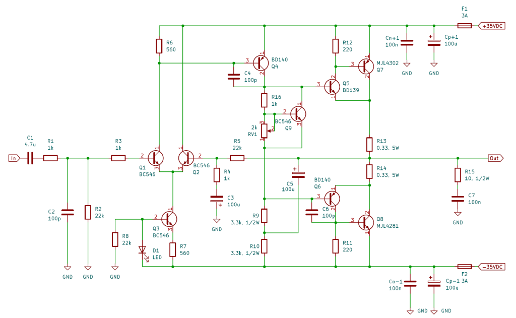
I won’t go into much detail about how the amplifier works, Rod does a very good job of describing that, I’ll just point out some “gotchas” or particularities. I also won’t repeat a lot of the same things that can be found on his website, so I strongly encourage you to read the pages for the P3A, P33, DC source and DC blocker.
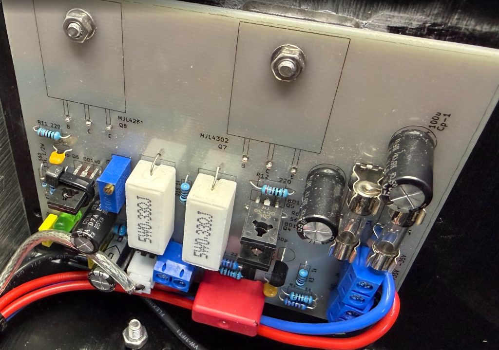
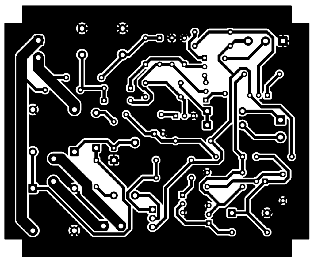
First of all, I built the PCBs myself. You can order from Rod’s website boards for many modules, if that’s convenient for you, but I wanted to do it all myself. You could also design the PCB and order PCBs from a PCB supplier. I built the amplifiers as 2 mono boards and mounted them on the left and right heat sinks of the chassis. I admit I used pictures of Rod’s assembled PCBs to place the components roughly where he did, since his layout is well designed and tested, it didn’t make sense to reinvent the wheel.
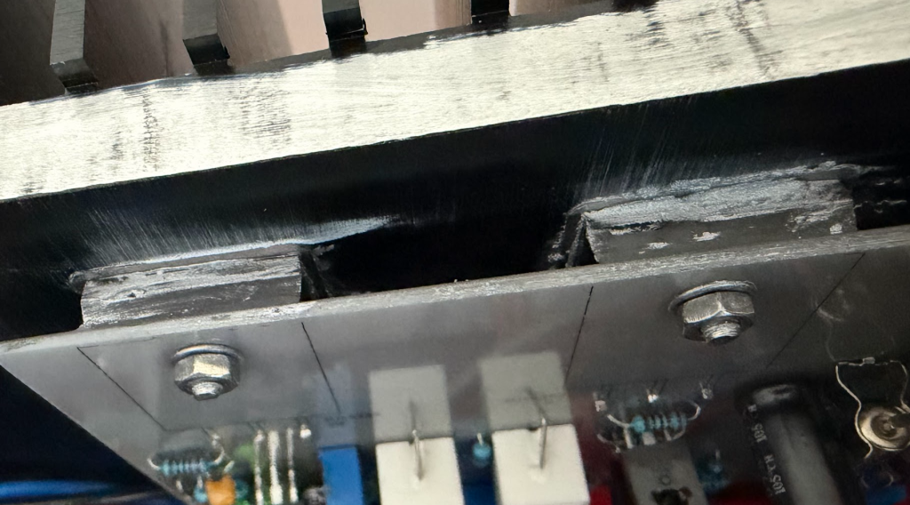
The final MJL 4302/4281 transistors (BTW, you can find alternatives on Rod’s website) are sandwiched between the PCB and the heat sink. When assembling the PCB, temporarily mount the transistors to the board with screws, use a marker to know where to bend the terminals; remove the transistors, bend the terminals at 90° and insert the terminals on the PCB holes from the Copper side (I used one-sided Copper PCBs). Solder the terminals, cut the ends from the other side, but make sure to leave 1mm to be able to measure the bias current in case you do it after you mount the boards on the heat sinks. Use mica or other type of electrical insulator and thermal paste between the transistors and the heat sinks. The collector of the transistor is electrically connected to the metal part of the body.
I didn’t mount any of the other transistors on a heat sink and they run fairly cold, even at high power. Still, when powering the amps with more than +/-35VDC, you might need additional heat sinks, see Rod’s explanations.
Don’t forget to clamp together Q6 and Q9 for thermal stabilization. You can use a small zip tie.

To get low noise and better precision, use metal film resistors. You can recognize them by their blue color and the fact that they have 5 bands.
Also, capacitors require some attention. C1 should be non-polarized film; the 100pF C2, C4, C6 should be ceramic; C3, C5, Cp+1, Cp-1, electrolytics; Cn+1, Cn-1 and C7, film.
Pay attention to the resistors that require larger than 1/4W power, especially R9 and R10, they do get a bit hot. Of course, R13 and R14 should be 5W cement type.
The LED should be a regular green LED. This is used to get a reference voltage, so don’t use any other color.
For power supply and speaker connectors, I used KF301 connectors with 2 poles, very easy to use and reliable. For audio input, JST XH2.54 connectors with 2 pins. Use shielded cable between the BT module and the amplifiers. You’ll need a crimping tool to crimp the cable wires to the connector pins. I used an Engineer PA-09, you can find it easily from most suppliers.
The thickness of the PCB traces was chosen to support the currents they carry, with the thickest ones, at 3mm connecting the GND and the final transistors collectors and emitters. There are no jumper wires required on the component side.

I didn’t have any issues with the amplifier boards, they worked perfectly at first power up. Make sure to adjust the bias current, the procedure is described on Rod’s page. RV1 should be multi-turn, so that the adjustment is easy and precise.
The power supplies
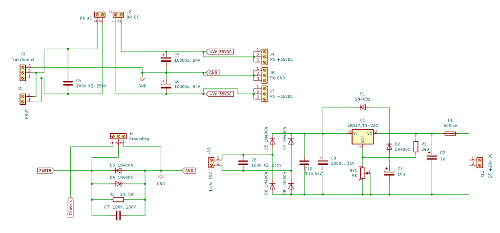
When I started testing the amp boards together with the Bluetooth module, the plan was to power the BT from the same +35V/GND rail as the amps, using a step-down converter. But what I found out was that this was creating a ground loop that introduced a lot of noise in the amps. So I decided to build a separate supply for the BT module, using a smaller 15V transformer. The second supply, with the rectifier diodes and step-down adjustable IC LM317 is on the same PCB, but separate in/out. I adjusted the voltage for the BT module to around 12VDC. The board supports up to 32V, but it has its own step-down circuit that generates a lot of heat when powered towards the upper end of the range and, being glued to the PCB heats up the filtering caps. So I mounted LM317 on a small heat sink that gets a bit hot but it doesn’t damage other components.
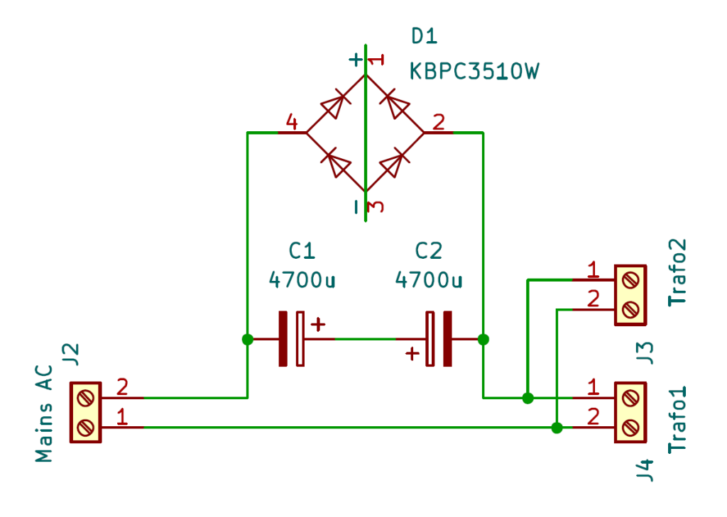
J1 connects to the rectifier bridge AC terminals and J2 to +/-. I used a KBPC3510 bridge mounted on the heat sink.
Special attention needs to be given to the ground traces on the power supply board. The ground connections leaving the power supply should be connected as close as possible with the capacitor terminals and the transformer median point, with minimal resistance. Running the ground exit points from different areas of the board creates small potential differences. Because the filter capacitors handle large ripple currents, this can easily induce hum in the amplifier. GND fill is not recommended as well. I redesigned the PCB 3 times due to the ground loops and the decision on the separate power supply for BT. As much as possible, the ground wiring should be star-shaped, with the center being the transformer median point and filtering capacitors.
There is a connection between the protective earth connected to the chassis and the DC ground. This is done through the D3/D4/R2/C7 ensemble. Don’t connect the mains earthing directly to the amp GND.

I used a glue gun to secure the large capacitors in place. They are tall and heavy, the connectors might get damaged in time due to vibrations.

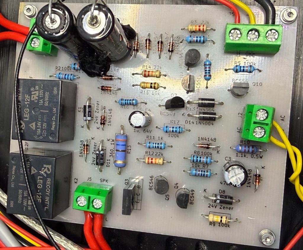
DC protection and muting

This type of amplifier, without a capacitor on the output, runs the risk of damaging the speakers if the final transistors are damaged and Emitter and Collector are shorted; 35V going to a speaker would likely destroy it. So DC protection circuits are put in place to disconnect the speakers if DC is dented on the amplifier output. This schematic uses relays to accomplish this. Another useful feature is muting for powering on a off the unit. Some amps send a “booming” noise to the speakers at power on or off. To solve this, a muting circuit would connect the speakers only a few seconds after the power on button is pressed and disconnect them as soon as the power button is released and not wait for the large filtering capacitors to discharge.
There are 3 diagrams on Rod’s website that accomplish these functions. All of them are getting power and GND from the +/-35V rails of the amplifiers, and it’s actually recommended to get the power from the same power supply in order for the logic of the circuits to work properly.
The DC protection that takes as input the output of the amplifiers and detects DC with D1-D6 diodes and C1/C2. Make sure to use non-polarized electrolytical for C1 and C2. The muting circuit uses the ~35V AC from the transformer to detect if the power button is pressed. And finally, both circuits output to the third circuit that commands the relays, you can spot the connection labeled as “Off”. This circuit uses C3 to delay the power on. If the signal on the Off input drops due to DC presence or AC off, the relays switch the speakers to GND immediately. The values of R10 and R13 are calculated based on power supply and relays characteristics, see Rod’s website for that. Using the voltage and relays (LEF-12F) on my diagrams, you can use the values on the schematic. No need for a radiator for Q3. The relays get a bit warm during normal operation, no need to worry, that’s normal; the coils stay energized and they release some heat. If they get so hot you can’t keep your finger on them, that’s a problem that needs to be investigated.
In terms of wiring, the board will need the +/-35V rails, GND, amps output L/R and the AC from the transformer secondary winding. I used GND for the speakers from the amp boards, to keep it as short as possible.

Mechanical and electrical hum, ground loops
Audio amplifiers are not particularly hard to build, but one problem that many projects are plagued with is unwanted noise coming from the amplifier, either electrically or mechanically. If certain rules are followed, these noises can be kept away.
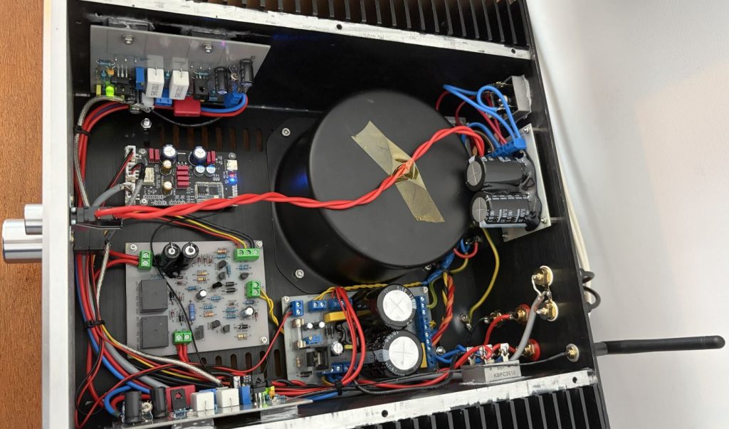
When I assembled the boards in the chassis and tested the amp with loudspeakers I was surprised to notice that I had a hum coming from the speakers. More so since the test outside the chassis, with the transformer and boards on my desk was nice and quiet. I thought about the transformer magnetic field inducing currents in the amps, but rotating it didn’t help much (sometimes it does). The real problem was that the wiring was all over the place. Low signal cables, speaker wires were passing close to the transformer. The speaker terminals were also close to the transformer, that’s where the pre-drilled holes were. I took the boards out, made new holes for the speaker terminals, RCA plugs and Bluetooth antenna, away from the toroidal transformer. Rerouted the cabling in a bundle on the sides of the chassis opposed to the transformer.
Blissful silence. At least from the speakers.
As I said, I replaced the toroidal transformer with a better quality one. But still it produced some hum. Although lower than the first transformer, the metal chassis was amplifying it, just enough that it was noticeable. I knew that DC in the mains supply can cause toroidal transformers to become saturated and hum but I didn’t have a safe way of testing for DC. I did have a test board with a DC blocker built from Rod’s website (basically a pair of eletrolytic capacitors protected by a rectifier bridge). Connecting the amp through the DC blocker resulted in the hum being drastically reduced. So I decided to build a simple PCB and use the same rectfying bridge and incorporate it in the amp chassis. Of course, if you don’t have DC in your mains, that is not necessary.

So lessons learned to avoid hum:
- Avoid cheap transformers
- Beware of counterfeit transformers
- Keep wiring away from the transformer (signal, speakers, DC power and ground)
- Twist AC and speaker wires
- Use separate power supplies for preamps and low signal modules
- Use DC blockers if you have DC on the mains supply
Final thoughts
I’m very happy with the outcome. The quality of the sound is remarkable to my ears. I can’t hear a noticeable difference from my Yamaha RX-A550 receiver. The sound is detailed, doesn’t lack in any part of the spectrum, punchy and bold when needed. Doesn’t sound harsh or too soft, like some reports I’ve heard of P3A. Would I have paid less if I bought an amplifier with similar specs? Probably. But the experience of building it from (almost) scratch makes it all worthwhile. I had a hell of a good time designing the PCBs in KiCAD, etching the boards, soldering the components, testing, resolving issues. And the pleasure of listening to it is only enhanced by this experience.
A phone recording it doesn’t do it justice, but here’s a listen of the amp paired with my Dali Zensor 7 floorstanders. Ignore the mess my 5 year old daughter did on the TV with kid’s makeup.
Special thanks to Rod Elliott for taking the time to share with us his vast knowledge in the audio and electronics field, making possible projects like this.
I’m attaching the KiCAD files I created for all the PCBs, if you’d like to use them.
Must read:
60-80W Power Amplifier
Loudspeaker Protection and Muting
Power Supply for Power Amplifiers
Mains DC and Transformers
Super proiect. Sa il vedem la munca cat de curand!
Munceste deja, de o luna imi gadila urechile.